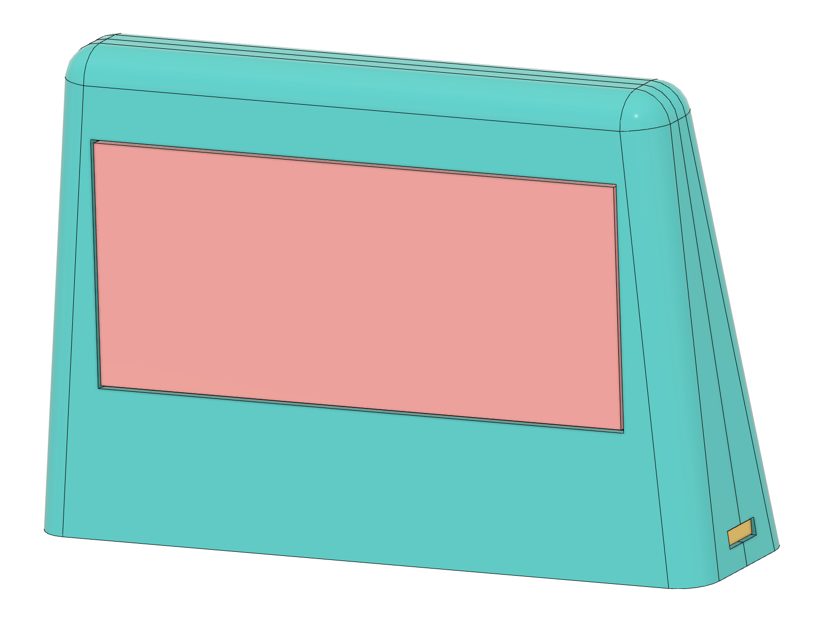
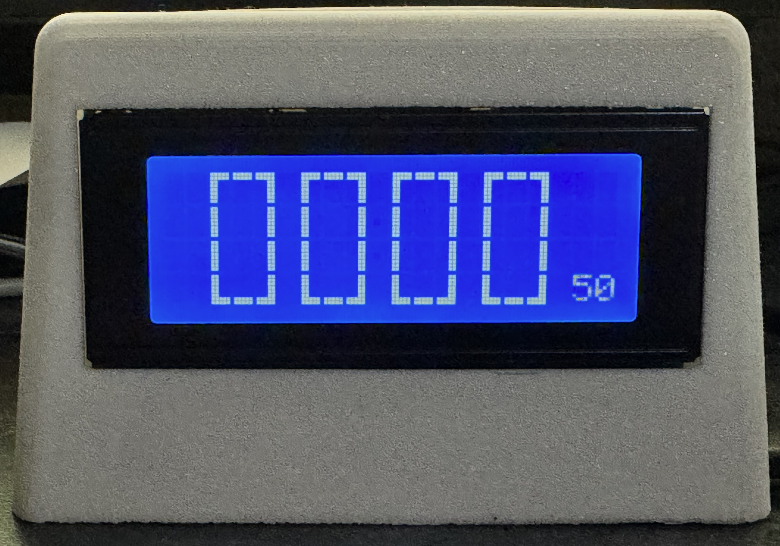
After playing with the Pi Pico 2W at the New Year, I had a little time today and made an OCaml-powered clock in a 3D-printed case.
It’s overcomplicated; I have two cores available, and I really wanted to use both of them, so core 0 handles the NTP sync, leaving core 1 to handle the display refresh. The code is written in OCaml 5 using my ARM 32 native code backend.
Here’s my pinout:
| Pi Pico | Label | LCD Pin | Label |
|---|---|---|---|
| 38 | GND | 1 | VSS |
| 40 | VBUS 5V | 2 | VDD |
| 3 | VO | ||
| 21 | GP16 | 4 | RS |
| 5 | RW -> VDD | ||
| 22 | GP17 | 6 | E |
| 24 | GP18 | 11 | D4 |
| 25 | GP19 | 12 | D5 |
| 26 | GP20 | 13 | D6 |
| 27 | GP21 | 14 | D7 |
| 29 | GP22 | 15 | K |
| 16 | A -> VDD |
- VO is connected to the centre tap of 100K potentiometer
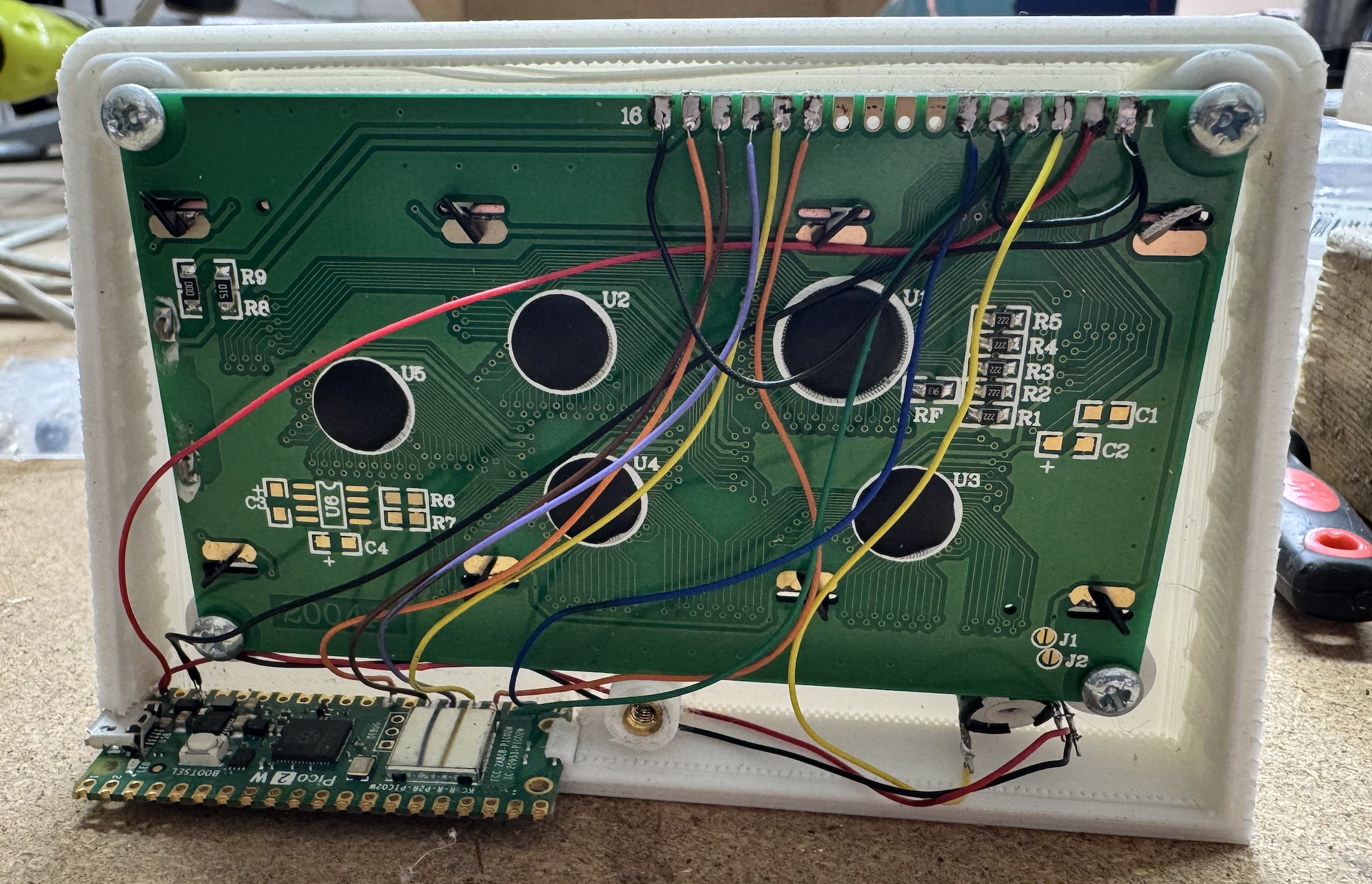
The LCD 2004 is the kind without the I2C backpack. I have used four GPIO lines driving the HD44780 in 4-bit mode for easier wiring.
The backlight is controlled by PWM pin 22 on the Pico, allowing it to be dimmed at night.
I’ll post my post in the next few days once I have tidied it up a bit.