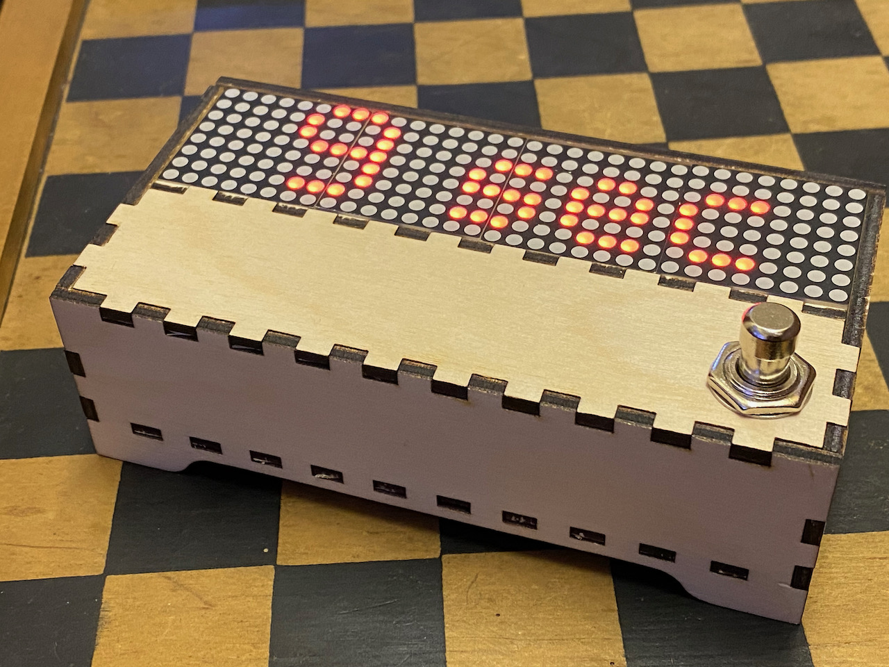
At the end of a quarter peal there is always the question of how long it took and whether anyone really noted the start time. Mike proposed a foot operated timer.
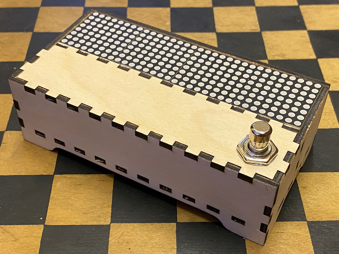
I wanted the display to be large enough that it can be seen while standing and I choose this MAX7219 dot matrix display from Amazon. This turned out to be a bit of a bad purchase but more on that later.
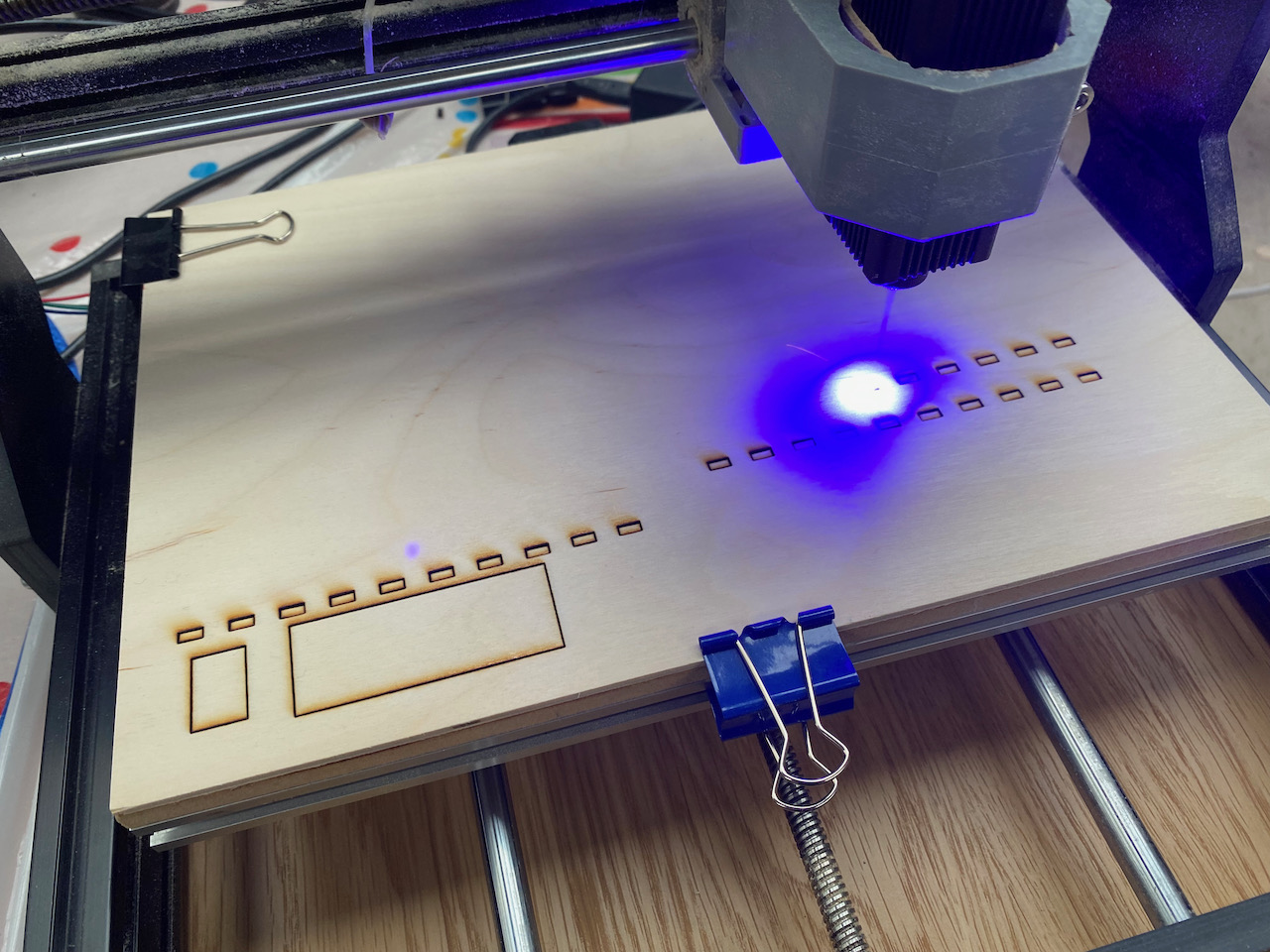
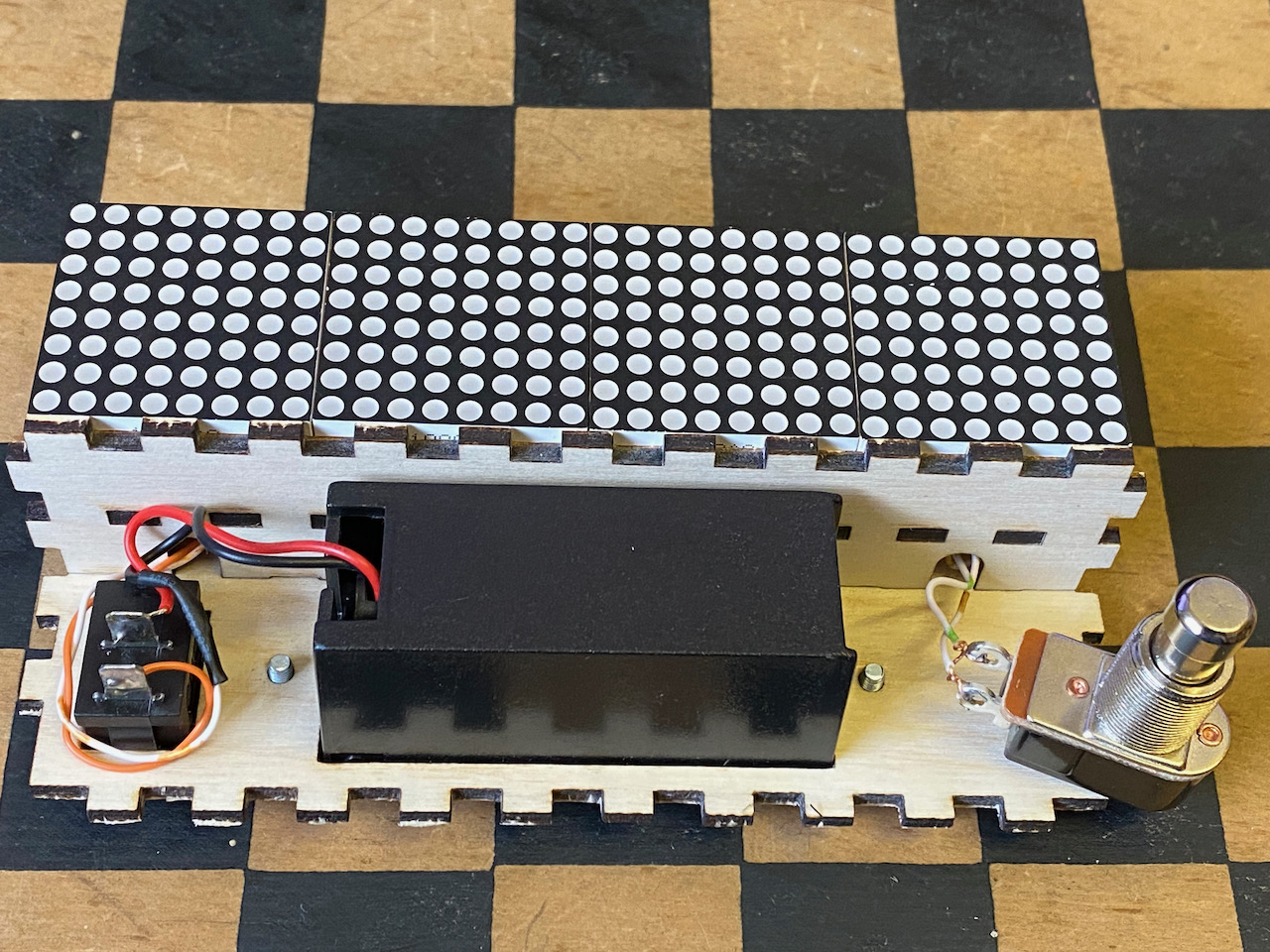
Using boxes.py to created the basic box that was just large enough to accommodate the display, battery, on/off switch and foot switch, I modified the design in Adobe Illustrator to shorten the top and add in a shelf for the display to sit on.
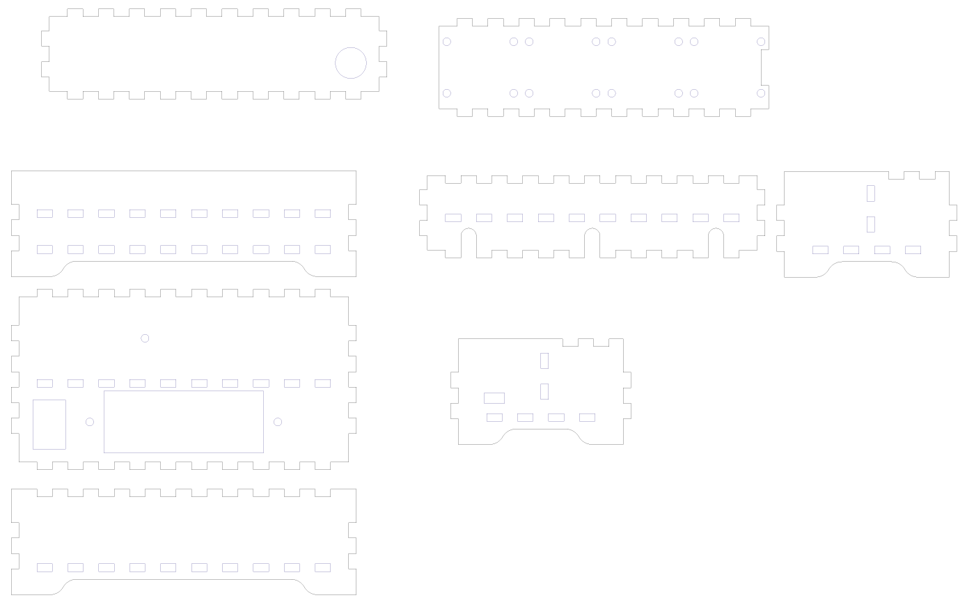
This was cut on the laser cutter.
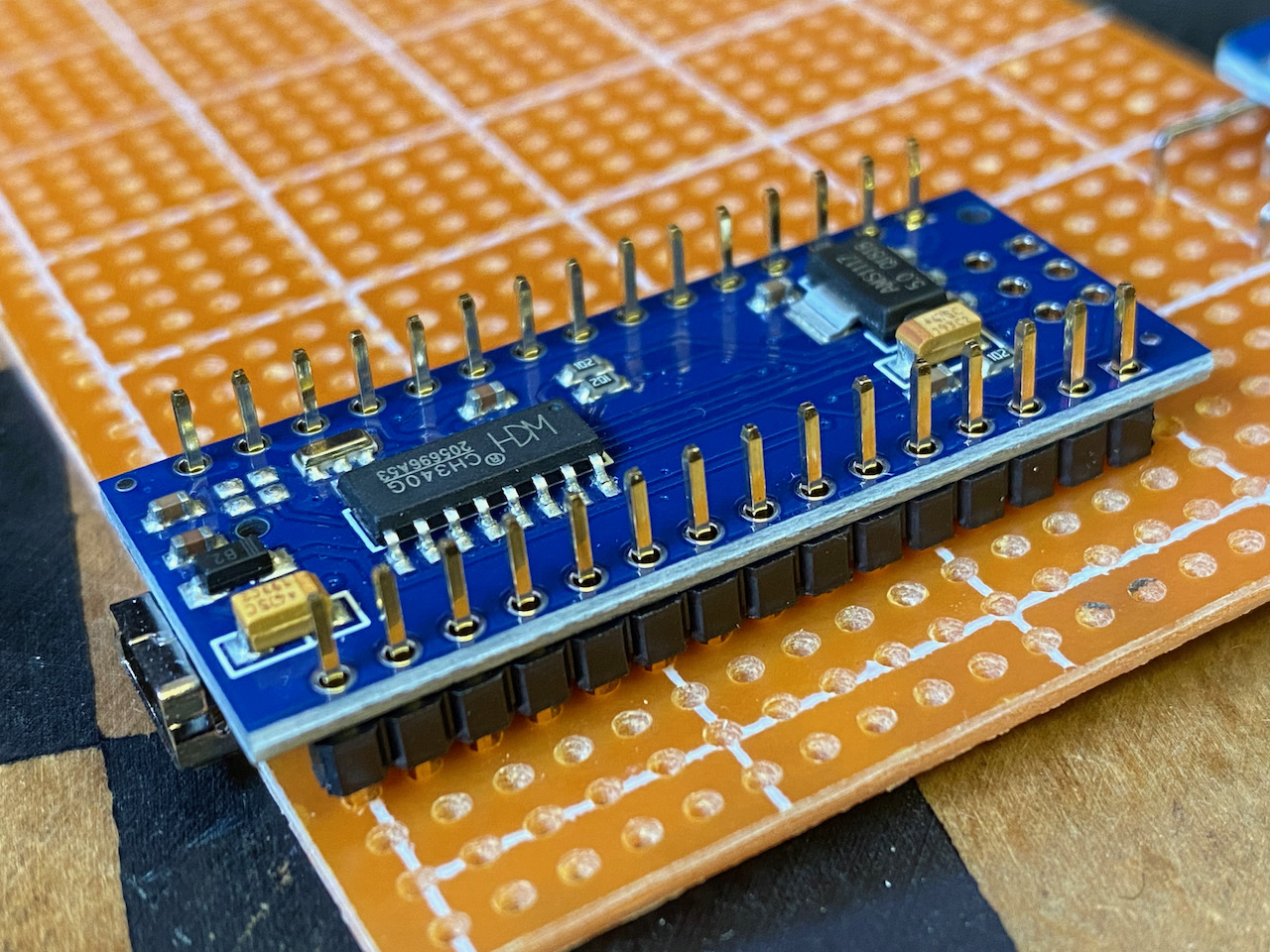
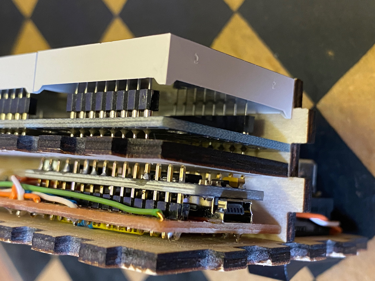
When assembling the electronics it became apparent that it would have been better to have a slightly taller box, but rather than waste the materials I decided to mount the Arduino upside down thereby fitting in a height of 12mm.
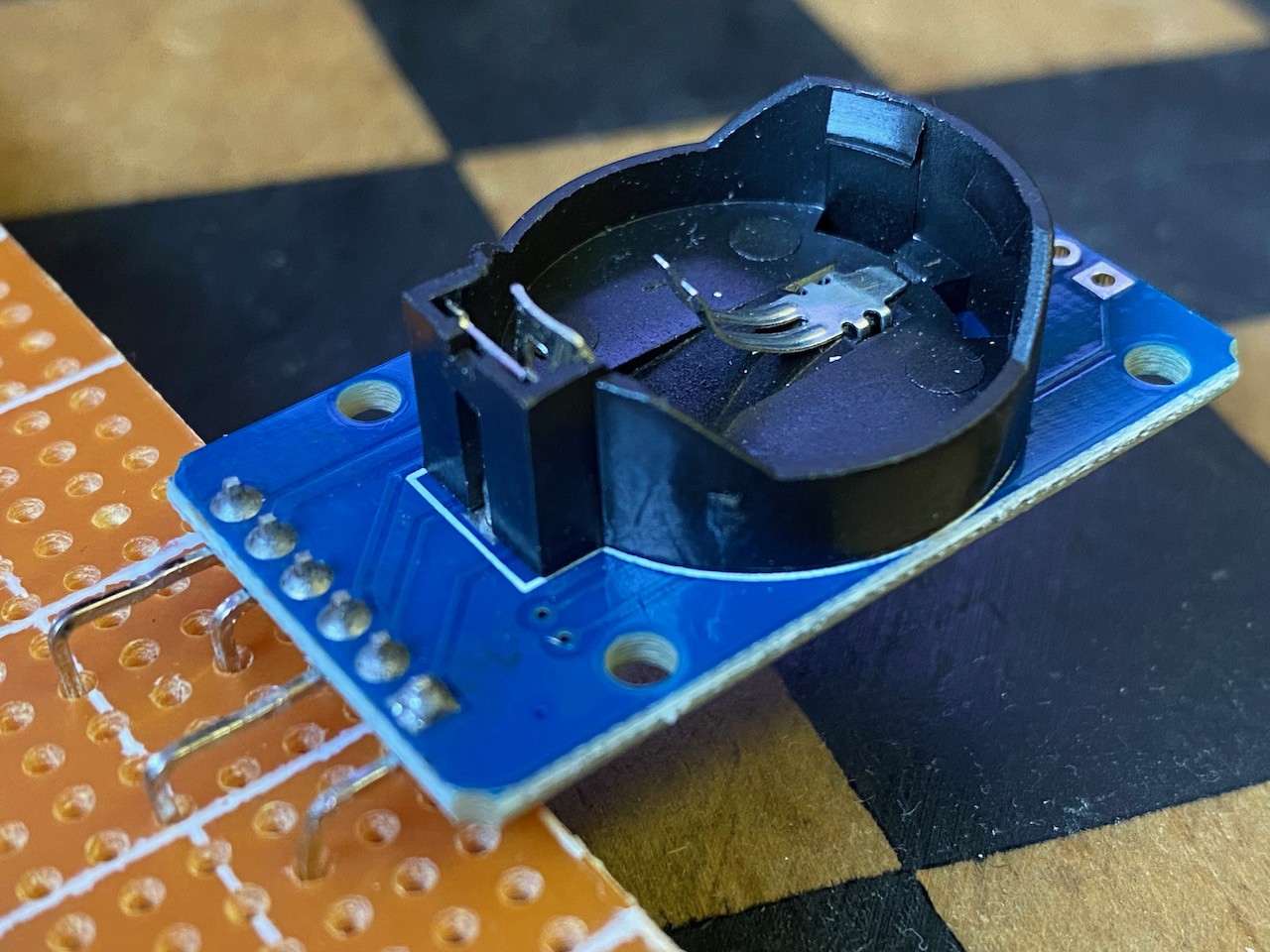
The DS3231 real time clock module was modified by bending the pins to fit in with the vero board spacing. Ultimately the battery holder was also removed to save space.
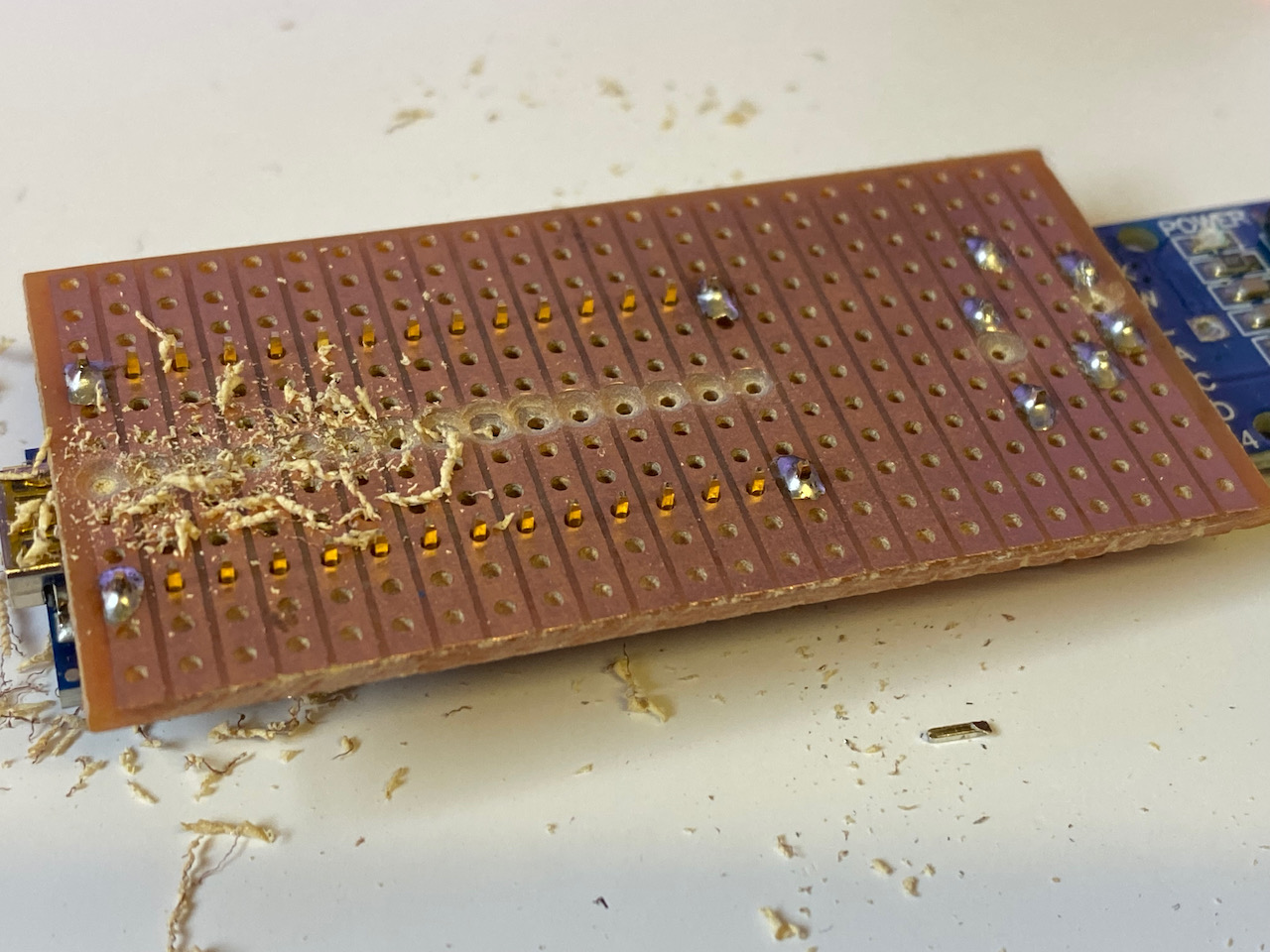
The vero board was drilled to cut the tracks.
After the initial assembly, the unit was tested on battery for the first time. This showed that it didn’t actually run on batteries. The code just crashed randomly after the display was initialised. Reading online on this post I found the problem with cheap display units!
Most of the cheap generic modules have very low values for RSET, which would significantly increase the power/current required by the module. This seems to be 10kΩ for the eBay specials, for a segment current exceeding 40mA, the specified minimum value for RSET in Table 11 being 11.8kΩ for VLED = 2V.
The full data sheet is available from Maxim
I had some 100KΩ surface mount resistors in 0603 format left over from another project. These were smaller than the 0804 format resistors used but they were relatively easy to change. Fortunately these fixed the problem.
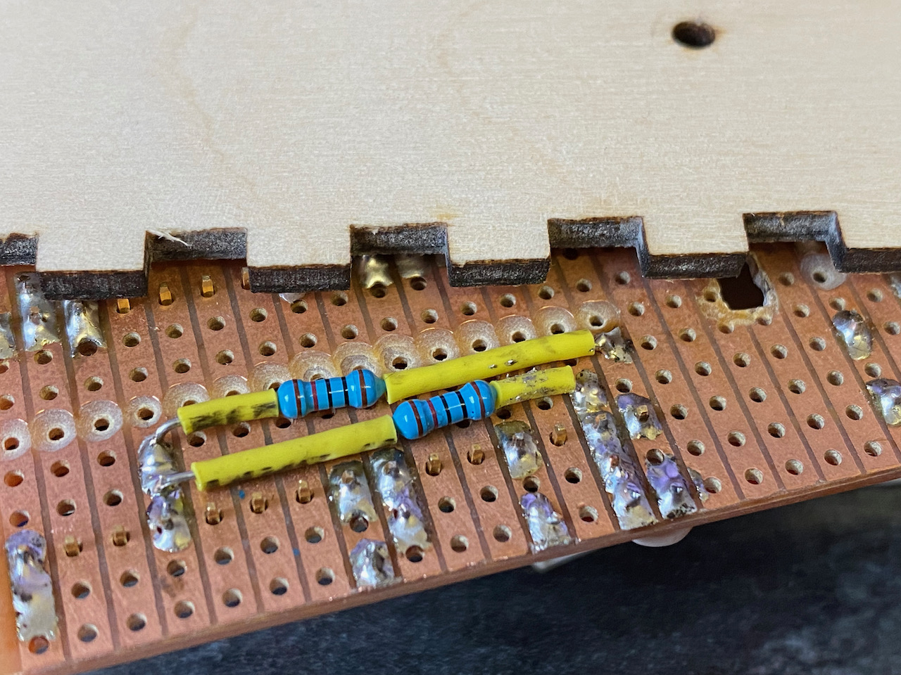
As an after thought a voltage divider was added to pin A0 to measure the battery voltage.
I wired the I2C bus from the Arduino to the DS3231 and the square wave output from the DS3231 to pin 2 on the Arduino. Pin 3 was connected to the push button. On the Arduino Nano only pin 2 and 3 can be used for interrupts. This configuration gave lots of options when it came to the code which wasn’t actually written yet!
Assembling the rest of the box was straight forwarded although a bit fiddly.
The code is available on GitHub